Sep 11
Medeco Biaxial Mortise – My Cutaway
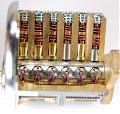
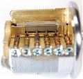
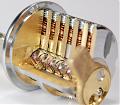
The Medeco Biaxial is the previous generation of Medeco lock, however it is arguably a more secure cylinder than the newer M3. Involving almost as much complexity as the M3, it is frequently a hard lock to explain to others. While there are factory cutaways of this lock (similar to the M3 in the previous post) they do not effective in showing the unique features of Medeco locks. To be able to show people how Medeco locks really work I decided to make my own Medeco cutaway. This is also my first milled cutaway for the blog.
The Biaxial lock is based on a decades old design by Medeco of a pin tumbler lock with the additional requirement of rotating pins (Medeco Classic). The Biaxial lock added the feature of fore and aft cuts to the Medeco Classic lock, with the tips of the pins skewed slightly towards either the front or rear of the lock. This means for every pin length (1-6) there is not only a rotation (left right center) but also the fore or aft position, making a total of 36 different varieties of bottom pins. The fore and aft cuts are primarily for expanding master keying possibilities, although it can also allow one key to operate more than one differently(non-master keyed) locks. This is due to the fact a single key can carry both a fore and aft cut for each pin, although some key bittings will not allow this as having both fore and aft cuts on one pin position will affect the MACS (maximum adjacent cut specification). It varies from the M3 primarily in its lack of a slider and by having a narrower keyway than the M3 (which is a large reason why the M3 is a less secure lock in comparison to the Biaxial).
Originally the Biaxial was not the first lock I was going to do a cutaway of, however a friend (Jonathan King) was giving two presentations involving his picking of Medeco cylinders and so we thought it would be useful to have a cutaway. Unfortunately due to some video issues it was not used in the presentations, but all the same, the cutaway was made. I actually made three of these cutaways, with this blog covering the final version. The first cutaway was simply for practice and finding any significant flaws in the design of the cutaway. The decision to make a third cutaway was done after seeing a cutaway by Tobias Bluzmanis (of Marc Tobais and Tobias Bluzmanis from security.org) and noticing further improvements that could be made. If you are to attempt to do something similar I suggest you read the entire article through (and wait for my next article on milling which should be out very soon) so that you have a complete understanding of what I did. I would also like to thank Han Fey for his suggestions and Mike Brewerton for being kind enough to review and edit this article prior to publication.
Let’s start with the tools required to do this:
-
End mill bits (various diameters are helpful for different cuts, I used 1/2″, 3/8″, 1/4″ and 1/16″)
-
Sharpie marker (for marking where we want to cut)
-
Cutting Oil (for finishing passes on the mill, leaves a nicer finish)
-
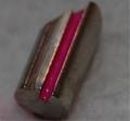
Paint brush w/ bright paint (for highlighting the sidebar groove in pins, I used fuchsia colored water based acrylic paint)
-
JBWeld (for adding a stop on the tailpiece so the top pins do not fall down)
-
Files for cleaning up cuts as needed
-
Parallels (used for ensuring the lock is level in the vice)
-
A Mill and a vice
Now we need to identify what the primary features are of the Biaxial that we want to show:
-
A normal pin tumbler setup (showing the pin chambers and shear line)
-
Rotation of individual pins (ability to see the sidebar groove in the pins)
-
Interaction between the sidebar and the pins (the sidebar teeth entering the pin grooves)
-
The pin interaction with the key itself (ability to see the bottom of the pins contacting the key)
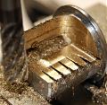
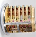
To accomplish this we will want to remove the maximum amount of material from the shell. If you look at the shell from the front we want to remove the top right quarter completely and almost the same on the bottom right quarter leaving a slight gap between the two where the sidebar groove is located. The difference between the quarters is on the bottom we will leave a small sliver of metal to ensure the sidebar remains retracted during rotation. During my first attempt I did not leave this metal and while the sidebar was still primarily retracted by the front of the shell the back part came out slightly causing it to get caught when re-entering the sidebar groove or the non-cutaway part of the shell. On the plug we will want to make similar cuts removing most of the top right quarter and bottom right quarter so you can see the bottom pins and their interaction with the key respectively. Finally we will want to remove a small part of the sidebar retaining part of the shell and plug so that you can see the sidebar interaction with the pins. For all of the millings I wanted to ensure that you could see all six pins in all parts. That means removing as much of the material as possible (sometimes in an extra step or two) to ensure you can see the pin closest to the front of the plug (for example). I did this so there would be no mystery step during demonstrations where if you could only see four of the pins you would not know what is going on with the other two.
The first step is to break down a Medeco biaxial lock. I suggest removing the hex screws in each of the plug chambers(a 5/64″ hex wrench works well) and removing the pins and springs that way (to avoid possible loss when taking the plug out). Then removing the cam screws and cam, and finally sliding the plug out with the sidebar. You’ll need to rotate the plug slightly to retract the sidebar before you’ll be able to slide it out of the shell. Keep in mind the sidebar springs and the hardened crescent inserts so you don’t lose them during disassembly. If the lock is somewhat dirty you most likely want to clean it at this point (to ensure your cleaning doesn’t tarnish the freshly cut surfaces). I used an ultrasonic cleaner to help make all the parts shine.
We are going to want to start off with the hardest cuts whenever possible, that way if a mistake is made we have less work we have to scrap. To this end we want to mark the bottom quarter of the shell off for making the cuts and to leave the middle sliver. I then wanted to go just a bit farther than half way past the center of the bottom of the shell (to give a good view of the tips of the pins). You want to cut down to right above the sidebar groove in the shell to offer maximum visibility but still allow the sidebar to properly lock into the groove. When locking the shell (or the plug for that matter) into the vice I have found it easiest to grip it by the face and back of the cylinder (and make sure to lock it down tight). I have tried several other ways of locking round objects into the vice, however if it is not very sturdy and the lock jumps while cutting it can cause damage to the lock, to the bit, or something else if it shoots off (I have had it happen). We want to mount the cylinder basically upside down for the first cut. You will also want to use parallels to raise the lock high enough above the lip of the vice to be able to cut as low as you want to be able to cut.
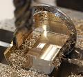
I started with the 3/8″ bit as it was the only bit that could comfortably fit between the middle sliver and the front of the plug. The lock is made up of primarily brass so I felt comfortable taking off about twenty one hundredths of an inch per pass. There will be two separate cuts we will be making, the back part of the lock near the cam and the front part between the sliver we plan to leave and the front of the plug. I started with the back part and moved on the X axis for the passes (back to the front). With the 3/8″ bit I ended up having to move on the Y axis after getting fairly far down and making side by side passes to remove all of the metal. On the front part I made passes on the Y axis and then at the end widened it on the X axis once I was all the way down, progressively making the sliver thinner until it was the correct width.
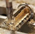
Next we can go after the top right quarter. This is an easier cut as we are just taking out the entire segment. You will want to mount the lock on its side rather than upright for this cut for two reasons. First of all your bits are round that means they will always leave a round corner somewhere, without proper planning that round corner can restrict the view of something important (mounting it normally would mean the pin closest to the front would not have good visibility). Second of all, while this cut is easier for the most part, the finish is very crucial. We are going to be milling down just barely into each of the pin chambers to give a good view of what’s going on inside. When mounting the lock in the vice it is extremely important it is completely level front to back and side to side. The parallels will take care of front to back (as long as you are careful, however for side to side leveling you will need to slowly clamp down on the plug while watching the letters on the face of the plug (or something else) to make sure you have it perfectly on its side. This is all to ensure when we get down to cutting into the pin chambers we cut into them all evenly and it looks good. You will be able to make minor corrections when you get to that point if needed, but do your best ahead of time.
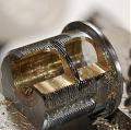
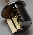
When you start to get close to the pin chambers (look at how far you have to go through the plug) you will want to only take 5-10 hundredths of an inch off on each pass so you don’t go too deep too quickly. If you go too deep here your pins and springs won’t stay in the chamber and that is game over. Once you start to cut into the first pin chambers it is important to finish that pass and look at the cut. If you are lucky you will cut into all the pin chambers equally and the bottom and top will both be cut in evenly. On my second attempt at this lock I got it even, on the third I did not. As you can see in the picture the bottom of each of the pin chambers was not cut into, but the top was. If this happens you can slightly back off your vice and roll the lock in the proper direction just a little bit to try and correct your offset. Make another pass (you should not need to go down any further) and see if you have it corrected. It may take a few tries (always better to move it too little than too much), but once you have it all set make your final pass. You want to cut down just far enough so you can see into each of the pin chambers, maybe about a quarter of the way into them at most. If you cut any deeper your lock may not function correctly.
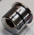
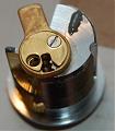
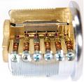
Next I flipped the lock so it was mounted normally in the vice, as I wanted to do two things. First I wanted to cut a small groove out so you could see where the sidebar was retained in the plug. I used the 3/32″ bit and just cut down slightly into the sidebar groove (I did this by entering from the right side when mounted. Second I wanted to remove the rounded corner from the front part of the piece of metal left to hold the sidebar in place. This is as easy as getting the bit at the right height and then just barely going forward enough to touch the front of the plug (and moving on the y axis then to remove any corners). Once you are finished with these optional steps you are done with the shell. The picture on the right shows the shell (with one of my earlier plugs that I cut) once complete.
Next we move onto the plug, we are going to want to remove the top right and bottom right quarters from it, along with cut into the sidebar retainer so that we can see it interacting with the pins. I got the idea for this cut from a very nice Medeco cutaway by Tobias Bluzmanis used in his and Marc Tobias’ latest book. The only downside to this cut is you can’t show the entire sidebar as we have to leave some metal in place to retain the sidebar. I decided to show four of the six fingers which is a nice portion of the sidebar but leaves plenty of metal to keep it in place. In addition, when we cut out the top right quarter we are going to want to follow a similar procedure to when we did the shell, as we are once again going to be cutting into the pin chambers. There is one final trick to cutting the plug, the hardened metal inserts. These do run the entire height of the plug and while it is possible to cut them with the right bits I strongly suggest against it. When doing my practice of this lock I did cut into one on the bottom and it damaged my bit slightly. So if you have DRO controls do the top first and mark how far on the X you can go (as you can see them on the top) so when you flip the plug over to do the bottom you don’t go too far (without DRO controls just measure twice and cut once).
I started with the top right quarter and mounted the plug on its side. Cut down slowly (traveling on the X axis) and do your pin chambers as you did on the shell. Make sure not to get too close to the sidebar retainer on the Y axis as you want it to stay firm. Once you are done with this side you will want to do the bottom right quarter. I mounted this sideways in the vice, and you are going to go down until you hit the keyway. When you get close to the keyway the metal may bend up when your bit hits it. After this happened I evaluated the options of attempting to cut this off, but in the end just moved into it with the endmill bit and it was able to go through it without any problems.
Finally on the plug we need to mount it normally and cut into the sidebar retainer. This is a bit of a tricky cut as I wanted no rounded edges. To make that happen I started in one of the plug chambers and moved on the Y axis all the way to the outside of the plug. Then I moved along the edge (on the X axis) of the chambers down to the second to the front chamber and went into this one and across on the Y axis again to cut the area out. I used the 3/32″ bit for this as it had to fit through the hole in the plug chambers without cutting the sides.
At this point you are basically done with the milling. Before re-assembly there are two additional steps you may want to perform. First item is to apply some sort of stop on the tailpiece so that the rotation of the plug is restricted. If you rotate the plug counter-clockwise once the pins are loaded into it, the top pins will drop into the cavity we cut out in the bottom of the plug. On the first cutaways I added a screw to stop the plug from rotating too far, however on this lock I forgot. I tried to inform a few people just not to rotate it counter-clockwise, however moments after this they frequently turned it the wrong way anyways. I was on the road at the time without my tapping equipment but knew I needed to apply some sort of stop, so I experimented with JBWeld. It is an epoxy-like substance that works very well with metals, so I figured I’d use this to make a stop for the tailpiece. The only trick when using JBWeld is to score the surface prior to application to help ensure a firm hold. When doing the counterclockwise stop you will want to make sure you get it as close to the tailpiece as possible to ensure the sidebar does not come out of the groove (as otherwise it won’t go back in easily). For the clockwise stop it is less important and I just applied it to the shell where the sidebar groove is.
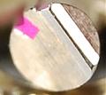
Next is painting the pins. I painted the sidebar groove in each pin so that once assembled it is far easier to follow the rotation of each pin. While you may be able to paint directly in the groove with a small brush, I always found that I couldn’t stay in the groove. The good news is that you can paint the groove and then quickly wipe the pin with your finger to remove any excess paint; if necessary a little water can also help. You will find that if someone was to insert the key and turn the plug slightly then turn the lock upside-down the bottom pins will fall out. You may not think this would happen very often but you would be surprised, and after searching for those pins on the floor three or four times you will want a solution to make this a great cutaway. While thinking about this problem one night I thought about the fact that if you could seal the bottom of the grooves the sidebar would keep the pins in the lock when it was retracted into the plug (which is the only time when they could fall out anyway).
Now this may sound familiar if you know the history of Medeco (or some of the recent exploits) but I will give a quick summary all the same. There are tools (as old as 30+ years ago) that allow you to hook into the groove of a standard Medeco bottom pin and manipulate the lock open much easier than normal. To counter this Medeco came out with pins where the bottom was sealed back at the end of the Medeco Classic’s life. Later on they made more complex closed grooved pins called ARX pins which had additional security features. There are a few issues with ARX pins however, for one they restrict the bottom pin heights as on some of the shorter pins the sidebar teeth stick out the bottom of them. This means fewer key combinations and a decrease in security. In addition ARX pins have a higher production cost, so they are still not standard in Medeco locks.
While my cutaway doesn’t really need the security of ARX pins it actually makes the cutaway function better (pins won’t fall out). The first thing I did was try to obtain a few ARX pins which have sealed grooves, however these are in quite short supply. My next solution was simply to do it myself, I tried with hot glue and a few other substances but they all caused issues during operation. I then found the best way was simply to paint the very bottom of the groove (about 10-15 times) to build up layers of paint and close it off. One very important note about closing the grooves on the pins is that all the pins must be at least size three or longer, otherwise you can end up with the sidebar needing to stick out the bottom and the sidebar fingers not being able to enter the pins (technically L/R/C rotation may allow some other shorter pins to also work).
Finally you are ready to re-assemble your completed cutaway and admire your work. In the end this is the most complete Medeco cutaway I have ever seen and works fantastically at being able to explain the way Medeco locks work to others. See the gallery for additional pictures.
3 Comments so far
Leave a comment





That is some remarkable work ! It is nice to finally see someone make different cutaways such as your Abloy 362, which I still can’t get over. Keep up the good work !
Thanks for the cutout. NOW I finally know how the biaxial works. For the longest time, I couldn’t picture how this works, until now. Very clever of Medeco, and thank you!
slot
Making The Cut – Mitch Capper